


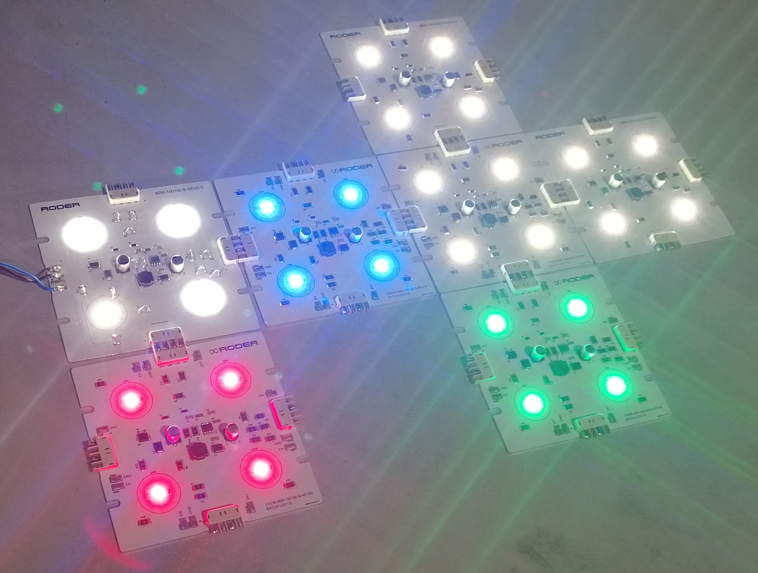
Machine vision systems are capital investments. The total project cost takes in cameras, lenses, lighting, processing hardware, software, integration labour, commissioning, and ongoing maintenance. Of these pieces, illumination is often underrated both in what it contributes to system performance and in its impact on total project cost. Poor lighting choices add cost in several ways: they push the team toward higher-specification cameras and lenses to make up for weak image quality, they stretch integration time through repeated setup iterations, and they spawn field service calls when the system cannot perform reliably in production.
Smarter lighting choices trim project cost at every stage: specification, integration, commissioning, and operation. The decisions that matter most are illumination geometry, wavelength, intensity margin, thermal management, and platform modularity. Each of these has direct, measurable consequences for the overall project budget and for the ongoing cost of keeping the vision system running throughout its service life.
The Real Cost of Under-Specified Illumination
The most common illumination mistake in machine vision projects is under-specification. The team picks the cheapest illuminator that seems to work during laboratory trials and moves on to integration. In the field, the system fails intermittently. The failures get blamed on the vision algorithm, the camera settings, or variation in the parts being inspected. Hours of troubleshooting go by before the root cause is pinned on insufficient or inconsistent illumination.
Under-specified illumination usually shows up as insufficient intensity margin. If the illuminator delivers just enough light at the camera for a correct exposure under ideal conditions, any change in the working distance, the part surface finish, the ambient light level, or the LED output from thermal drift will drop the system below its operating threshold. The result is inconsistent performance and high false reject or missed defect rates that are hard to diagnose and expensive to fix once the system is installed.

Do you want help choosing the product?
Specifying Intensity Margin at Design Stage
A well-designed illumination system holds a minimum intensity margin of 30% to 50% above the minimum operating threshold under worst-case conditions. That margin absorbs the combined effects of LED ageing, thermal output reduction, variation in part surface reflectance, and working distance tolerance. Building this margin in at the design stage costs nothing: it just means choosing the next size up in the illuminator range or trimming the working distance slightly. Finding out the margin is too small after installation costs many times more in troubleshooting, modification, and downtime.
Illumination Geometry: Getting It Right First Time
The geometry of illumination decides what the camera can see. Choose the wrong geometry and the camera never sees the defects or features the inspection has to detect. No amount of image processing can recover information that was never captured. Getting the geometry wrong at the prototype stage means redesigning and replacing the illuminator before integration, which adds cost and delay.
Prototyping with Geometry Flexibility
RODER Vision illuminator families include several geometry options: direct matrix, ring, flat dome, darkfield, backlight, and bar illuminators. Prototyping with representative samples from each geometry category before committing to a production-quantity order is cost-effective. The time spent in the prototype phase testing different geometries is small next to the cost of reworking an integrated system after a geometry error surfaces in production.
Many projects gain from a combination of two illumination modes: one for the primary inspection task and a second for a secondary task such as crease detection or surface contrast enhancement. Designing for dual illumination from the start, with separate strobe-triggered illuminators for each mode, is far cheaper than retrofitting a second illumination channel after the system is built.
Wavelength Selection and Camera Compatibility
Wavelength selection shapes both the image quality and the system cost. Using the right wavelength for the specific inspection task can let a lower-cost camera reach the same detection performance as a more expensive camera under sub-optimal illumination. The silicon sensor in a standard monochrome camera peaks in the red and near-infrared band, between 600 nm and 900 nm. A red or near-infrared illuminator takes full advantage of that peak sensitivity and maximises the signal-to-noise ratio in the image.
Avoiding Over-Specified Cameras Through Better Lighting
A common cost driver in machine vision projects is over-specifying the camera to make up for poor illumination. If the light is too weak or produces too much image noise, the team may upgrade to a camera with a larger sensor, lower read noise, or higher pixel count to recover image quality. A higher-specification illuminator matched to the sensor sensitivity is almost always the lower-cost route. The illuminator cost increase is a fraction of the camera upgrade cost, and the resulting image quality gain is usually greater.
Strobe Illumination: Efficiency and Cost Reduction
Strobe illumination cuts the electrical power draw of the illumination system while delivering higher peak intensity than a continuous-mode illuminator of the same physical size. For inspection on moving production lines, strobe mode is almost always the right call. The mix of lower average power consumption, longer LED service life from reduced thermal stress, and higher peak intensity for motion-freeze tasks makes strobe illumination the most cost-effective operating mode in the majority of industrial vision applications.
LED Service Life and Replacement Costs
LED service life in machine vision illuminators leans heavily on operating temperature. A LED running at a junction temperature 10°C above its rated maximum lasts roughly half as long as one running inside its rated thermal envelope. Industrial machine vision systems usually run 24 hours a day, 365 days a year. At these duty cycles, a factor-of-two difference in LED service life translates straight into doubled replacement and maintenance costs over the system lifetime.
RODER Vision HTTM technology actively controls LED junction temperature, holding it within the optimal range whatever the ambient temperature or drive current variation. That extends LED service life and cuts how often the illuminator has to be replaced. For a production system running continuously for five to ten years, the maintenance saving from extended LED life is substantial and belongs in the total cost of ownership calculation when comparing illuminator options.
Modular Illuminator Platforms and Long-Term Cost
Machine vision systems are often modified and upgraded across their service life. The inspection requirements shift as the product range evolves. New defect types join the inspection list. Production speeds climb. A modular illuminator platform that supports format changes, wavelength changes, and intensity upgrades without replacing the whole illuminator assembly cuts the lifecycle cost of the vision system markedly.
RODER Vision Modular Bar Illuminators
RODER Vision modular bar illuminators are assembled from standard segments in defined lengths. A bar illuminator that has to be extended to cover a wider field of view is extended by adding more segments. The wavelength can be changed by swapping the LED modules within the existing mechanical housing. This modularity removes the need to redesign and replace the complete illumination assembly when inspection requirements change, cutting the cost of system upgrades substantially.
Integration and Commissioning Cost Reduction
Integration and commissioning time is a sizeable slice of machine vision project cost. Illuminators that are hard to mount, align, and adjust add integration hours. Illuminators that need custom brackets or non-standard mounting interfaces add mechanical design and fabrication cost. Illuminators with complex or proprietary control interfaces add software integration effort.
RODER Vision illuminators use standard M4 and M6 mounting interfaces and come with C-mount and S-mount accessory threads for filter and lens accessory mounting. The strobe trigger interface works with 5V and 24V logic levels and can be driven straight from machine vision camera trigger outputs without extra signal conditioning hardware. These standard interfaces shorten integration time and remove the need for custom mechanical and electrical interface design.
Total Cost of Ownership: A Framework for Illuminator Selection
Total cost of ownership (TCO) for machine vision illumination takes in: the initial purchase cost, the integration and commissioning cost, the electrical energy cost over the system lifetime, the maintenance and replacement cost over the system lifetime, and the cost of downtime from illumination-related inspection failures. A low-purchase-price illuminator with poor thermal management, short LED life, and non-standard interfaces usually carries a higher TCO than a higher-specification illuminator from a professional manufacturer.
Judging illuminators on TCO rather than purchase price alone consistently leads to better project outcomes. The purchase price gap between a professional illuminator and a commodity unit is usually recovered within the first year of operation through lower maintenance, lower energy use, and fewer inspection failures. For a system running for five to ten years, the TCO advantage of the professional illuminator is very significant.
Products and Technologies
RODER Vision Illuminator Families for Cost-Effective Vision Projects
The RODER Vision product families below pair high performance, long service life, and standard interfaces to keep total project and ownership costs down.

DL6 — High Density LED Matrix
HTTM thermal management for long LED life and stable output. Multi-wavelength. Strobe compatible. Standard mounting and trigger interfaces for fast integration.

DL5 — High Intensity LED Matrix
High peak intensity in strobe mode for demanding inspection tasks. Low average power consumption. Long LED service life thanks to low duty cycle operation.

BL3 — LED Backlights
High uniformity backlight for silhouette and dimensional inspection. Available in multiple formats and wavelengths. Standard interfaces. High peak intensity in strobe mode.

DC6 — High Density LED Ring
Versatile ring illumination for a wide range of inspection tasks. Multiple diameters and wavelengths. Direct camera-axis mounting for fast setup and low integration cost.
Frequently Asked Questions
Contacts & Information
Contact for general information : info@roder.it
Systems and Sensor Integration Partner : www.roder.it
RODER Artificial Vision Division : www.visiotronix.com
RODER Instruments Division : www.innovacheck.com
More information about VISIOTRONIX : about us
The information on this website is provided for informational purposes only. Although it has been prepared with the utmost care, it does not constitute a contractual offer or a binding commitment to supply. It may contain transcription, translation, or typographical errors. For precise and up-to-date information, please contact our company directly.
Please note: Some images on this website have been intentionally generated using Artificial Intelligence (AI). This is due to the fact that, for many applications and projects, it is not possible to disclose photographs of the actual installation or system due to confidentiality agreements, contractual clauses, and Non-Disclosure Agreements (NDAs).
Related topics :
 UV LED Lighting for Fluorescent Leak Detection and Security Marker Inspection
 Reading Blurred Barcodes: Pairing Shutter Speed with Strobe Lighting
 Bright LED Bar Light Illumination for Scanning Oversized Parcels on Logistics Conveyors
Logistics Automation: High-Intensity Bar Lights for Large Parcel Scanning
Bright LED Bar Light Illumination for Scanning Oversized Parcels on Logistics Conveyors
Logistics Automation: High-Intensity Bar Lights for Large Parcel Scanning
 Machine Vision and LED Lighting for Precision Bottle Cap Inspection