


Machine Vision Lighting for Electronics and PCB Inspection
- Very small features and dense component layouts at high magnification.
- Highly reflective solder joints that demand controlled diffuse lighting.
- Tasks from component placement to solder, trace and marking inspection.
- Diffuse, coaxial and low-angle techniques selected per defect type.
- Each application note links to the matching RODER products and technology pages.
Electronics manufacturing demands the most precise vision inspection of any industry. Boards combine tiny features, reflective solder joints and very dense component layouts. Moreover, the materials mix matte silkscreen, glossy metal and dark plastic on one surface. Therefore, a single lighting geometry rarely solves every task. This sector hub introduces the inspection challenges of electronics and PCB production. In addition, it links each application note to the recommended technique and to the matching RODER Vision products.
Why Electronics Inspection Is Demanding
Scale is the first difficulty. Components such as 01005 chips and fine-pitch leads are extremely small. Consequently, the system works at high magnification with a shallow depth of field. As a result, uniform and bright illumination becomes essential for sharp images.
Reflectivity is the second difficulty. Solder joints behave like curved mirrors, so direct light produces harsh glints. By contrast, a diffuse dome wraps the joint in even light and reveals its true shape. Therefore, diffuse geometries dominate solder inspection.
Contrast is the third difficulty. Printed marks on black ICs offer almost no natural contrast. However, low-angle or directional light raises the relief of laser-etched characters. In addition, the right wavelength can separate a feature from its background.
Material variety is the fourth difficulty. A single board mixes matte solder mask, glossy pads, dark plastic and bright leads. Because each material reflects light differently, one source rarely satisfies every region. Consequently, integrators often combine geometries or capture several images under different lighting. As a result, multi-shot acquisition has become common in electronics inspection.
The Main Inspection Tasks
This sector groups several recurring tasks. First, component placement verifies presence, position, polarity and orientation before reflow. Next, solder joint inspection checks fillet shape, bridging, insufficient solder and tombstoning. In addition, trace verification looks for opens, shorts and etching defects on bare boards.
Marking inspection is equally important. Here OCR and OCV confirm part numbers, date codes and logos on ICs. Furthermore, connector and pin inspection checks coplanarity and bent leads before assembly. Finally, conformal-coating checks confirm complete, defect-free coverage under suitable lighting.
Recommended Illumination Techniques
Each task maps to a specific geometry. For solder joints and shiny components, dome and diffuse lighting suppress glints and show fillet shape. On flat boards, and for code reading, a ring light gives even, orientation-independent contrast. To expose etched marks and coplanarity, low-angle and dark field lighting raise surface relief.
Wavelength adds another degree of freedom. For example, red light increases contrast on green solder mask, because the mask absorbs it strongly. By contrast, blue or white light helps on bright metal and silkscreen. Moreover, RGB or multi-shot lighting separates colour-coded features in a single station.
Timing also matters on fast lines. Because pick-and-place machines move quickly, the light often runs in strobed or pulsed mode. Consequently, it freezes motion and keeps tiny features sharp. In addition, a stable current driver prevents brightness drift between boards.
Coaxial lighting deserves a special mention. When pads or lead frames are flat and mirror-like, on-axis light returns straight to the camera. Therefore, the flat areas appear bright while defects appear dark. Moreover, this approach reads engraved data-matrix codes on shiny metal. As a result, coaxial geometry complements the dome for specular electronic surfaces.
Recommended VISIOTRONIX Illuminators
Four illuminator series cover most electronics and PCB inspection tasks. The table below links each one to its product page, with the job it does on the line.
| Series | Illuminator family | Typical use | |
|---|---|---|---|
 | FD2 Series | LED Flat Dome Illuminators | Diffuse light that suppresses reflections on solder joints and metallised pads |
 | DC6 Series | LED Ring Illuminators | Even light around the lens for component presence and placement verification |
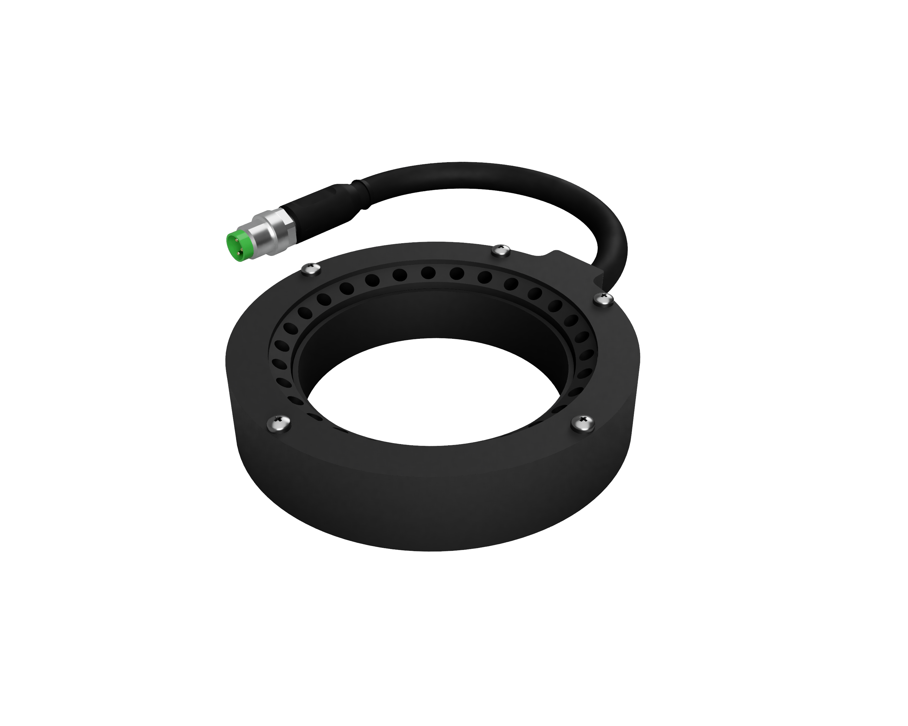 | DC2 Series | LED Ring Illuminators | Low-angle light that raises relief on markings, traces and lead coplanarity |
 | DL6 Series | LED Panel Illuminators | Uniform direct light over the full board for general inspection stations |
Most electronics tasks use a compact set of illuminator families. For solder and shiny components, choose LED Flat Dome Illuminators. On flat boards, and for code reading, use LED Ring Illuminators. To highlight directional marking and coplanarity, consider LED Bar Illuminators or focused LED Spot Illuminators.
Where boards are translucent or leads must be measured, LED Backlight Illuminators add a clean silhouette. Beyond catalogue options, VISIOTRONIX provides engineering support for OEM integration and custom geometries. In practice, the right mix of diffusion, angle and wavelength turns a dense board into a clear image. Therefore, start from the application note that matches your task, and then follow the links to the technology and product pages.
Automated Optical Inspection and Traceability
Automated optical inspection underpins modern electronics quality. Therefore, illumination must stay perfectly repeatable from board to board. Otherwise, even small brightness changes shift the measured solder area. For this reason, current-stabilised lighting is a basic requirement.
Traceability completes the picture. Every board carries a code that links it to its production data. Consequently, reliable marking and code reading depend on controlled, glare-free light. As a result, the same lighting principles serve both defect detection and full traceability. In short, this hub is the entry point for engineers lighting bare boards, populated assemblies and final electronic modules.
Application Notes in Electronics & PCB
The following application notes describe real electronics inspections. In each case, the note explains the problem, the recommended lighting and the related RODER products.

Component Placement
Precise LED illumination guides SMD pick-and-place robots. Therefore, ring lights, backlights and low-angle sources are selected for reliable placement verification.
PCB, Soldering & Trace Inspection
Controlled LED light reveals solder joints, components and traces. As a result, the system verifies fillets, continuity and IC marking with high accuracy.
Frequently Asked Questions
Diffuse dome lighting is usually the best choice for solder joints. Because the joints are curved and shiny, the dome wraps them in even light. As a result, the fillet shape becomes visible without harsh glints.
Black packages offer very little contrast under flat light. However, low-angle or directional lighting raises the relief of the etched characters. Therefore, the marking stands out and OCR or OCV becomes reliable.
Red light increases contrast on green solder mask, because the mask absorbs red strongly. By contrast, blue or white light works better on bright metal and silkscreen. Therefore, wavelength is chosen to match the target colour.
Automated optical inspection compares each board against fixed thresholds. Consequently, any brightness drift shifts the measured solder area or contrast. For this reason, current-stabilised, flicker-free lighting keeps results repeatable from board to board.

Do you want help choosing the right product?
Contacts & Information
Contact for general information : info@roder.it
Systems and Sensor Integration Partner : www.roder.it
RODER Artificial Vision Division : www.visiotronix.com
RODER Instruments Division : www.innovacheck.com
More information about VISIOTRONIX : about us
The information on this website is provided for informational purposes only. Although it has been prepared with the utmost care, it does not constitute a contractual offer or a binding commitment to supply. It may contain transcription, translation, or typographical errors. For precise and up-to-date information, please contact our company directly.
Please note: Some images on this website have been intentionally generated using Artificial Intelligence (AI). This is due to the fact that, for many applications and projects, it is not possible to disclose photographs of the actual installation or system due to confidentiality agreements, contractual clauses, and Non-Disclosure Agreements (NDAs).